Scenegraph Generation
In this tutorial we will generate a scenegraph tree from the beginning.
Visual Scripting
You don’t need to edit the xml files from a scripting editor. We provide a user friendly editor to load, generate and make all the necessary updates for your convenience.
The first step is to open the visual scritping editor, navigate to MAGES/SceneGraph Editor in the Unity Editor.
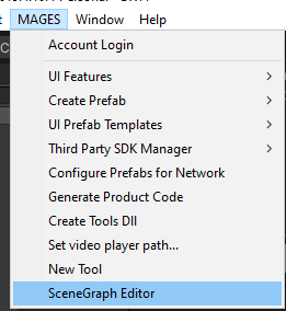
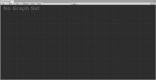
The visual scripting window will appear on your screen.
Controls
Controls for the Scenegraph Editor are depicted in the table below:
Left Click |
Select Nodes and drag them to place |
Right Click |
When clicked on a Node opens the option menu for this Node. Also used to generate new nodes. |
Middle Click |
Press the middle click and drag on the window to move around the editor. |
Scroll Wheel |
Zoom in - Zoom out. |
Create New Scenegraph
To create a new xml follow the steps below:
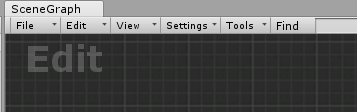
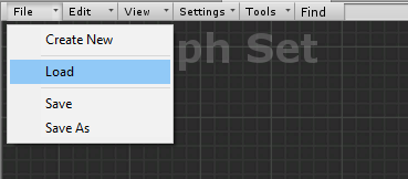
From the top menu click on File/Create New.
1.1. As soon as you create a new empty graph you will be set in Edit mode.
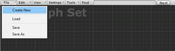
1.2. In Edit mode you can start editing the graph.
To create Lesson-Stage-Action (LSA) nodes, right click inside the window to open the node generation menu.
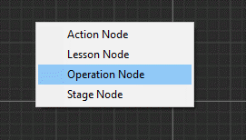
2.1. The first node you need to create is the Operation Node. This is the base node of the Scenegraph tree. To generate the base node click on the Operation Node button.
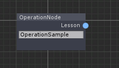
The Operation Node will appear on the editor. The next think you want to do is to set the Name. To do that click on the text box inside the node and type the name. You can drag the node around the editor by pressing and holding the right click on the node you created.
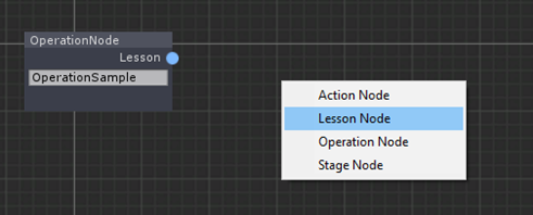
2.2. Now let’s create some Lessons. Press right click again and select Lesson Node.
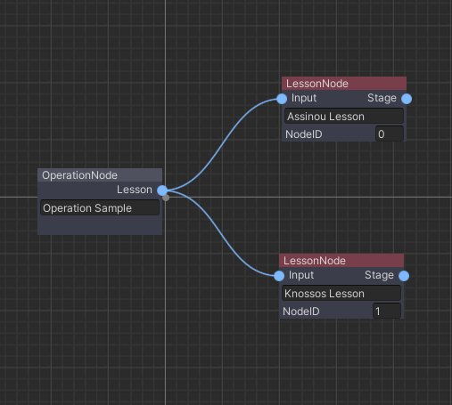
The Lesson Node will appear and is automatically connected to the Operation Node. Now you have to register two fields. First it’s the name of the Lesson and the second one is the NodeID. This value refers to the order of nodes.
For example, if you want this Lesson to be the third lesson of the Scenegraph, set NodeID=2 (numbering starts from 0). Below we have created two Lessons. Pay attention to the NodeIDs.
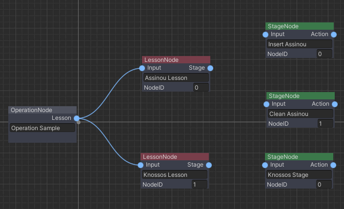
2.3. Applying the same methodology we will create some stages. Right click and select the Stage Node.
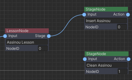
To connect the nodes together you right click on the right blue circle of a node (Output Node) and release the click on a the left blue circle (Input Node) of another node.
A small example below:
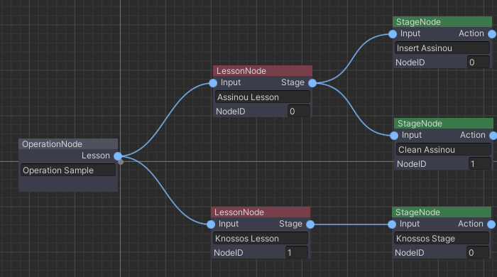
Now proceed to link all stages with their lessons. This is an image of the Scenegraph so far:
2.4. Now let’s set the Action Nodes. Right click and select the Action Node.
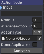
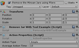
The Action Node has all the fields described above at the xml section, plus the NodeID to set the action order. The second to last field is to set the Action script. You can simply drag and drop your Action Script there or press the black circle on the left side to search it from there.
Note
Remember to drag and drop your Action Scripts!
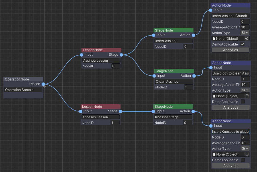
The Scenegraph tree is now complete.
Note
The Analytics button in the Action Node will be explained in the Analytics tutorial.
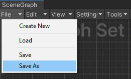
We are now ready to generate the Scenegraph.xml. Click on File/Save as.
A windows dialogue box will appear to save the file as an xml (If you click Save As, otherwise the Scenegraph will be saved on the existing xml). Insert the name of file and the xml will be saved. In this example we will name our scenegraph
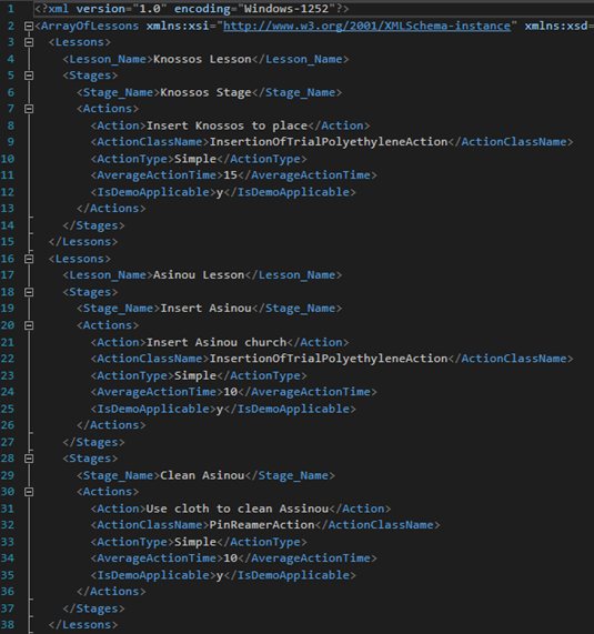
SampleApp.xml.The xml has been successfully generated!
Warning
All 4 XML files MUST be saved in a “platform” folder.
The final step is to configure the xml file in the unity scene.
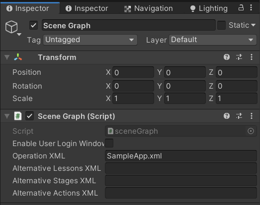
Navigate to SCENE_MANAGEMENT/Scene Graph gameobject and at the Scenegraph component add the xml name to the Operation XML field. In this case we write SampleApp.xml".
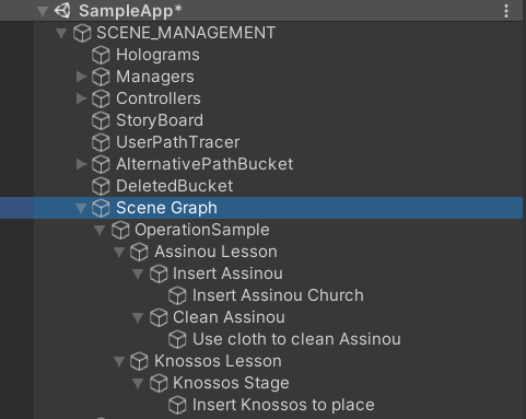
That’s it! Press play on the Unity Editor and you should see the scenegraph populate under the Scene Graph gameobject.
Extra Functionalities
Open an existing xml
If you want to open an existing xml go to File/Load.
Select your XML file from the windows dialogue box.
Generate Alternative Nodes
Alternative nodes can be created from existing Nodes. Right click on the node you want to make it alternative and select “Set Alternative Node” option.
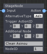
This will create the alternative path fields that you need to set.
The Trigger ActionID refers to the Action which will trigger the alternative path. For example a critical error in an operation may trigger an alternative path to change the flow of the procedure.
The Additional Node refers to the previous node of the alternative L/S/A you are going to ADD when the alternative path will triggered. In case of a RPL alternative node this will set the node that will be replaced by the new one.
Alternative Type field sets the type of alternative path (Add, Replace, Remove).
Note
To make the node standard again press again the “Set Alternative Node” option and the extra fields will be removed.
Warning
Alternative Nodes need to be saved only in the alternative xmls. The main xml containing the Scenegraph should NOT contain any alternative node.
Delete A Node
To delete a Node right click on the node and select the “Delete Node” option.
Clear All Nodes
To clear (delete) all the nodes press Tools/Clear Nodes.
Find Node by Name
To find a node by its name you can search for it in the Find region.

Type in the text box and click Next button to get the next reference on the Scenegraph tree.
Now we have a complete Scenegraph and we are ready to start the application. After successfully generating the Scenegraph, the “Scene Graph” gameobject will look like this in play mode.
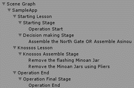
As you can see the Scenegraph gameobject has been populated with all the LSA Nodes from the xml importing. An example Action Node of Scenegraph will look like this.