First Insert Action
Introduction
Once you’ve finished setting up MAGES, you are ready to create your first insert action with MAGES. An Insert action involves the user manipulating an object to place it in a specific position designated by the designer of the action.
We’ll guide you through the implementation of this action step-by-step from content creation to the end.
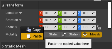
Note that, any position or rotation values that look like the following:
(X=1.000000,Y=1.000000,Z=1.000000)
can be copied from the documentation and pasted directly into the editor verbatim by right-clicking on the target property:
Overview
The Insert Action requires at least two blueprints:
The Insert Blueprint – the interactive item
The Final Blueprint – the location and orientation where this item is meant to be placed
A Hologram – Used to help guide the user visually
Creating the Insert Blueprint
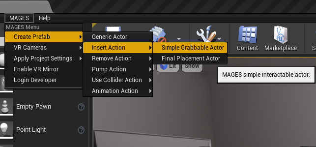
We’ll get started by opening the MAGES Menu, and selecting “Create Prefab” > “Insert Action” > “Simple Grabbable Actor”:
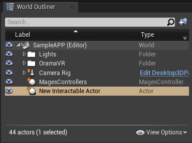
In the World Outliner, you should see a new actor named “New Interactable Actor”. Select it as shown below:
Let’s set the actor to show a very simple cube.
In the Details Panel, find and select the component named “StaticMeshComponent”:
Note
If you cannot see any components there, try deselcting the actor by clicking somewhere in the viewport, or on another actor in the World Outliner
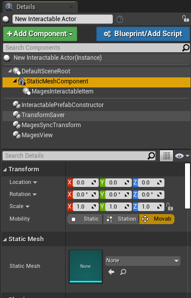
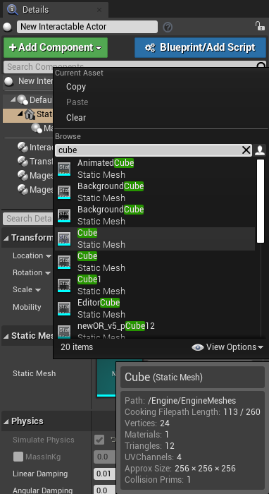
In the Component’s Detail panel, set the “Static Mesh” property to a mesh of your choice. For this example, we’ll use the “Cube” mesh.
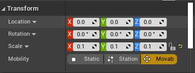
In this case, our cube is a little too big for something that would be realistically grabbable, so we’ll change its “Scale” property to (X=0.100000,Y=0.100000,Z=0.100000)
This is a bit more realistic now. Next up, we’ll move the actor to a more plausible location by doing the following:
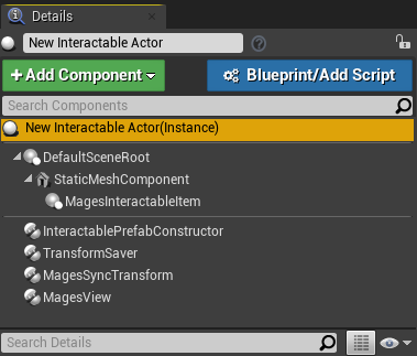
In the Components panel, select the “New Interactable Actor(Instance)” item so that any change we make will be applied to the actor’s transform, and not to the component’s transform:
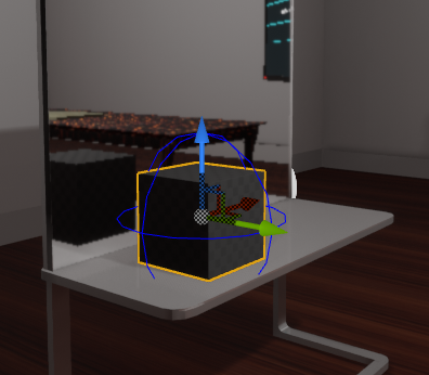
Now we’ll move the actor on top of the mirror surface (specifically, (X=0.001282,Y=-245.366364,Z=131.245087)):
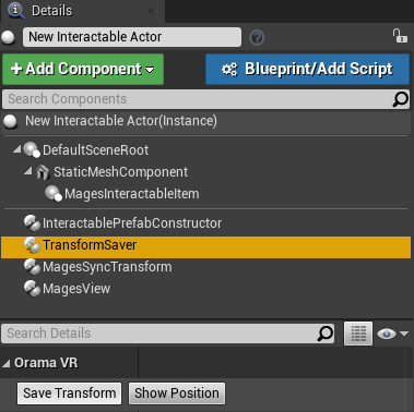
Afterwards, we have to save the Transform of the actor, so that it will be spawned at the exact position we’ve specified:
In the Components panel, select the “Transform Saver” component and below click the “Save Transform” button:
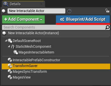
Finally, we need to convert this Level Actor into a blueprint. Click the “Blueprint/Add Script” button:
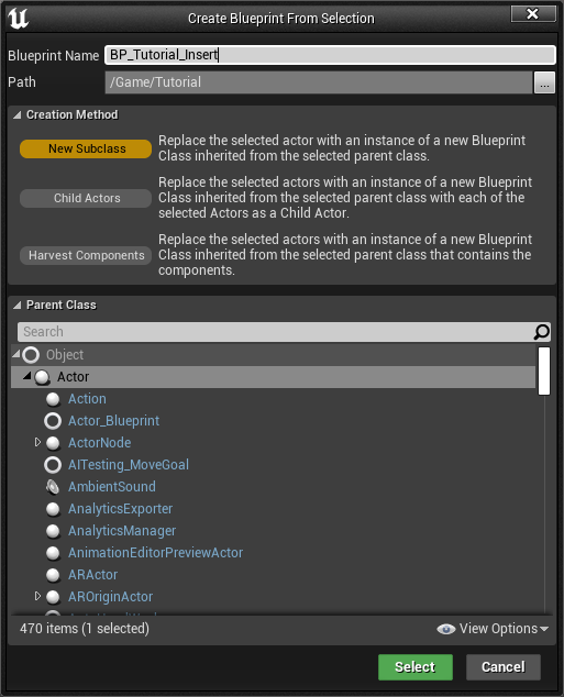
A prompt will open up, asking you for the name, and save location of the blueprint. For this tutorial, we chose to name it “BP_Tutorial_Insert”:
The blueprint will open in the editor. Save it and close the editor.
We have finished creating the Interactable Insert Blueprint! Now we can go about creating the Final Blueprint in a similar manner as with the Insert Blueprint (using the MAGES Menu), but most of the time, the Final Blueprint has very similar properties to the Insert Blueprint, so we’ll show you a faster way:
Creating the Final Blueprint
To create the final blueprint, we will duplicate the Insert Blueprint, and change some of its properties:
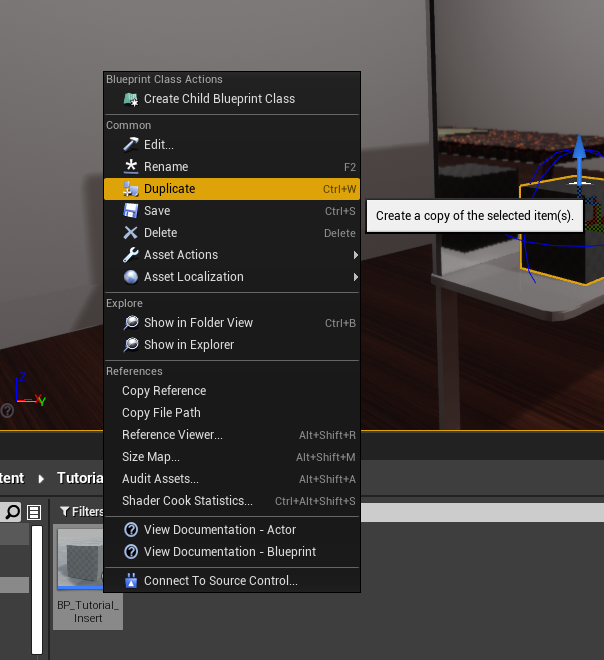
Find the Insert Blueprint inside the Content Browser (the name used in this tutorial is “BP_Tutorial_Insert”), right-click on it, and choose “Duplicate”:
A new Blueprint will be created; an exact replica of “BP_Tutorial_Insert”. We’ll name it something more appropriate, like “BP_Tutorial_Final”:
Now, open the Final Blueprint, and find the Components panel (in the top-left of the window):
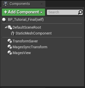
Delete the following components by selecting them, and pressing the Delete key on the keyboard, or by right-clicking and choosing “Delete”:
MagesInteractableItem
InteractablePrefabConstructor
The Components panel should now look like this:
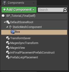
Using the “Add Component” button, we’ll add the following components:
Int Final Placement Prefab Construct
Prefab Lerp Placement
Additionally, we’ll add a “Box Collision” component as a child of the “StaticMeshComponent”:
Select the “Box” component, and in the Details panel on the right, set its Scale property to (X=4.125000,Y=4.125000,Z=4.125000)
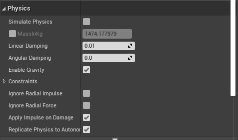
Next up, we have to configure the “StaticMeshComponent” so that it does not simulate physics, or collider with anything else:
Select the “StaticMeshComponent” in the Components panel, and in the details panel, find the section named: “Physics”. Make sure that “Simulate Physics” is unchecked:
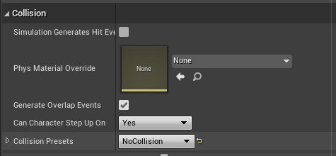
Just underneath this section, there is the “Collisions” section. Set the “Collision Presets” property to “NoCollision”.
Now, we need to configure the other two components we added so that this Blueprint works like a Final Blueprint.
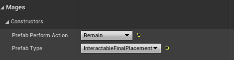
Select the “IntFinalPlacementPrefabConstruct” in the Components panel, and in the details panel set the following properties (under Mages > Constructors):
Prefab Perform Action: Remain
Prefab Type: InteractableFinalPlacement
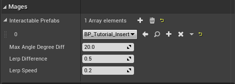
Almost there for the Final Blueprint! Select the “PrefabLerpPlacement” component. In the Details panel, find the property named “Interactable Prefabs”, and press the ‘+’ button next to it.
This allows you to declare which blueprints may be placed into this Final Blueprint; we’ll use just one for this action, namely “BP_Tutorial_Insert”:
Afterwards, press “Compile” and “Save” in the toolbar.
We’ve finished setting up the Final Blueprint, but remember, we cloned it from “BP_Tutorial_Insert”. This means, that its transform will be the exact same as the Insert Blueprint’s transform. Let’s change that:
In the Content Browser, find the “BP_Insert_Final” Blueprint and drag it into the level. You’ll see that it snaps to the exact position as the Insertion Blueprint.
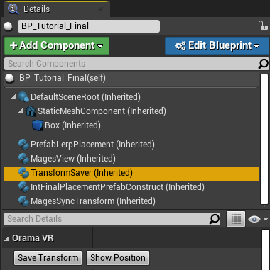
Let’s move it to the right of Insert Blueprint, specifically to (X=57.065460,Y=-245.366364,Z=131.245087). We need to save its Transform now, so as before, select the TransformSaver in the Details panel, and press “Save Transform”:
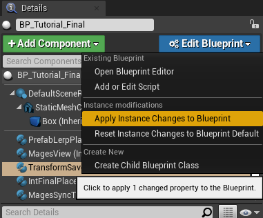
Additionally, we’ll apply the instance’s changes to the blueprint; to propagate the transform value:
Click “Edit Blueprint” and choose “Apply Instance Changes to Blueprint”:
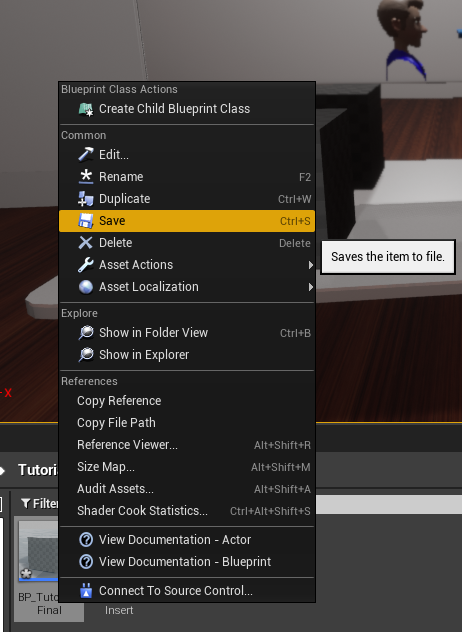
In the Content Browser, you will see that your blueprint has been marked with an asterisk icon. This means that it has unsaved changes; right-click on it and choose “Save”:
We are done creating the Final Blueprint. Now this action would work correctly, but how is the user supposed to know where to place the cube? Remember; the Final Blueprint will be invisible until the action has been completed. In real-world scenarios, context would help, but a hologram blueprint would be best. So let’s create it.
Creating the Hologram Blueprint
In the same manner as with how we created the Final Blueprint, we will duplicate the Final Blueprint, and make the necessary changes to turn it into a Hologram.
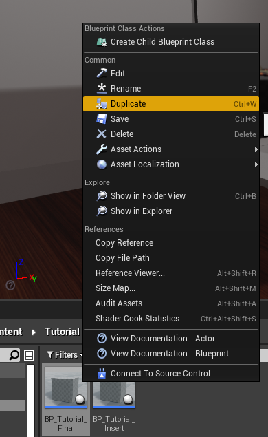
In the Content Browser, find the Final Blueprint (“BP_Tutorial_Final” in our case), right-click on it, and choose “Duplicate”:
Name it accordingly; we chose to name it “BP_Tutorial_Holo”, and afterwards, open the blueprint.
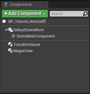
In the Components panel, find and delete the following items:
MagesSyncTransform
IntFinalPlacementPrefabConstruct
PrefabLerpPlacement
Box
You should have something like the following afterwards:
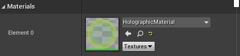
Now, we need to change the material of the cube, so that it looks like a hologram. Select the “StaticMeshComponent” and in the Details panel on the right, find the section titled “Materials”. Change the property “Element 0” to the “HolographicMaterial”:
Finally, hit “Compile” and “Save” to save the changes, and close the editor.
We’ve finished creating the Blueprints required for the Insert Action. Now we need to create the Insert Action Blueprint, and use the blueprints we’ve created.
In the Level, delete the following actors (they will be spawned when the action takes place):
Insert Blueprint “BP_Tutorial_Insert”
Final Blueprint “BP_Tutorial_Final”
Creating the Insert Action
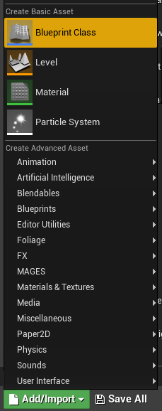
In the Content Browser, press “Add/Import” and choose “Blueprint Class”:
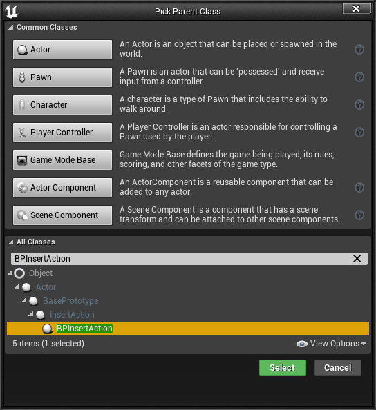
In the dialog, expand the “All Classes” section, and search for “BPInsertAction”, select it and press “Select”:
Name the new blueprint accordingly (we chose “TutorialInsertAction”), and open it.
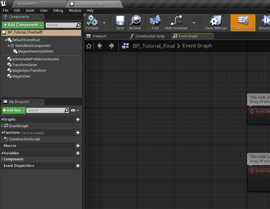
In the Event Graph tab, there are three nodes:
Event Initialize BP
Event Perform BP
Event Undo BP
Drag a connection from the “Initialize BP” node - a popup will appear with all of the available nodes. Search for “Set Insert Prefab” and hit Enter:
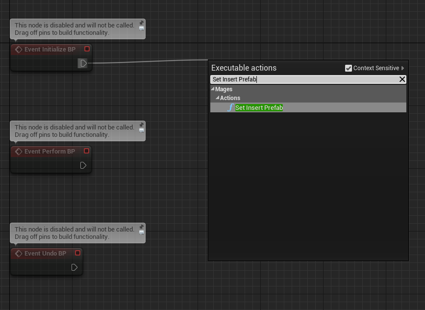
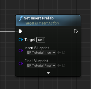
A new node will be created and connected to the “Initialize BP” node. With this node, we can declare which blueprints will be used for the Insert Action.
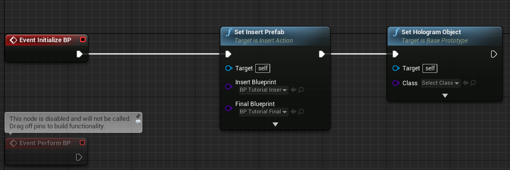
Set the Insert and Final Blueprint parameters to the blueprint’s we created earlier. It should look something like the following image:
Next up, let’s also add our hologram blueprint. Drag a connection from the output pin of the “Set Insert Prefab” node, search for “Set Hologram Object” and press enter.
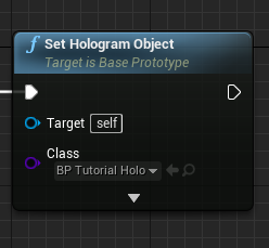
You should now have something like this:
Set the “Class” property to the hologram we created for the action (“BP_Tutorial_Holo”):
Done! Hit “Compile” and “Save”, and you can close the blueprint afterwards. Now, all we need to do is to add it to our Scene Graph.
Adding the New Action to the Scene Graph
Open the blueprint named “SceneGraph_SampleApp”. You can find it in the following path inside the Content Browser: “MAGES_SDK/Content/MAGES/Operation/ActionBlueprints/”.
In the Event Graph tab, navigate to the segment marked “Starting Stage”. We’ll add our action right after the Question Action of the Sample App Scene Graph.
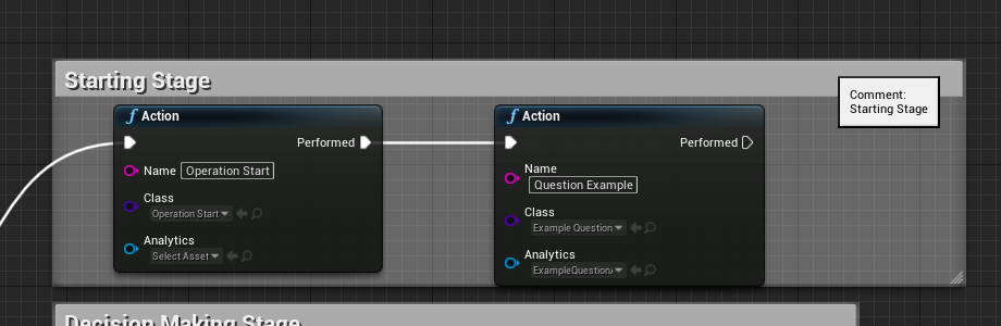
Drag a connection from the “Performed” pin of the “Question Example” node, search for “Action” and press Enter:
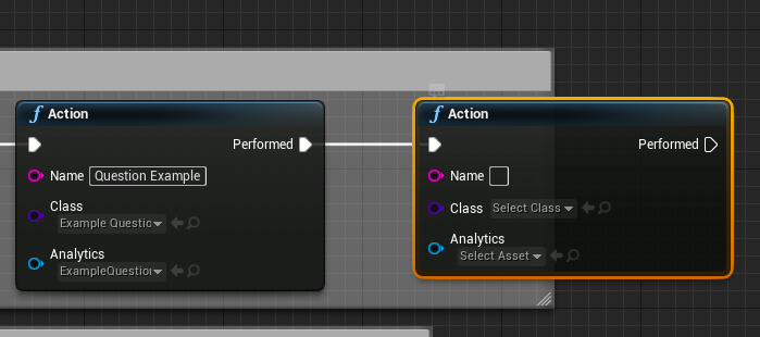
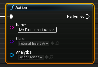
Se the “Name” property to something memorable, like “My First Insert Action”, and the “Class” proerty to the name of the action blueprint we last created (“TutorialInsertAction”):
Hit “Compile” and “Save”; you can close the blueprint editor afterwards.
We’ve added the action to the scene graph, and now we’re ready to test it out! By default, the Desktop 3D controller is used, so let’s look at how it works.
2DoF Controller Tutorial
The 2DoF controller is used to run a MAGES application in Desktop 3D mode, without the need of any HMD or controllers.
In this mode, the character is controlled through the keyboard and/or mouse/trackpad.
In Desktop 3D mode, the gameobject in the Unity hierarchy, which represents the camera is called 2DoFCamera.
A UI is available in this mode, by pressing the space bar. This will open the menu of 2DoF which gives the user the ability to move, rotate, lock the hands. Below, you can see the 2DoF menu on action.
In the following table, a detailed explanation can be found, regarding each button of the 2DoF Controller.
Button
Explanation
W or Up Arrow
Move forwards
S or Back Arrow
Move backwards
A or Left Arrow
Move left
D or Right Arrow
Move right
Q
Move downwards
E
Move upwards
F1
Toggle Body move mode
F2
Toggle Right Hand move mode
F3
Toggle Left Hand move mode
Tab
(Usually followed after pressing F1 or F2), enables the hand rotation mode with the use of mouse/trackpad
G
(Only after F1), enables/disables the cursor and freezes the camera rotation.
Left Mouse/Trackpad Click
Hand trigger on the hand targeted by F2/F3
Right Mouse/Trackpad Click
THand grip on the hand targeted by F2/F3
Ctrl
Switch hand plane movement (when F2 or F3 enabled)
Ctrl and Left Click or Right Click
Sends the Left or Right hand to the direction of the crosshair
You can utilize the Desktop 3D camera controller in order to run and execute the first insert action you created before. To do so, please follow the instructions below:
Ensure that the Sample App scene is open, and click the “Play” button in the level editor
You will be presented with a menu like the following. This is the Operation Start menu.
There are two ways to continue in this point. Either by pointing the crosshair Single Player button and clicking with the left mouse button, or by pressing the X button on the keyboard. It is recommended to continue with the latter for now.
Afterwards, the Question Action will appear, you can complete it by answering and pressing the “Submit” button, or by pressing “X” on your keyboard.
In this point, the “BP_Tutorial_Insert” we set up in the tutorial above, will be present in the level along with a hologram, atop the desk on the mirror to your left.
Move close to the cube using the W/A/S/D/E/Q buttons, and by moving the mouse to turn
Activate the virtual right hand in order to be able to pick up objects. To do so, press ‘2’ from the number row on the keyboard.
Using the mouse, move the hand towards the cube, and grab it using the left mouse button
Drag it towards the hologram to the right, and it will snap to that position
Building the Application
This section will demonstrate how to Package the project for the Windows platform, with your newly created Insert Action.
Open the Project Settings, and click the “MAGES Settings” section on the sidebar
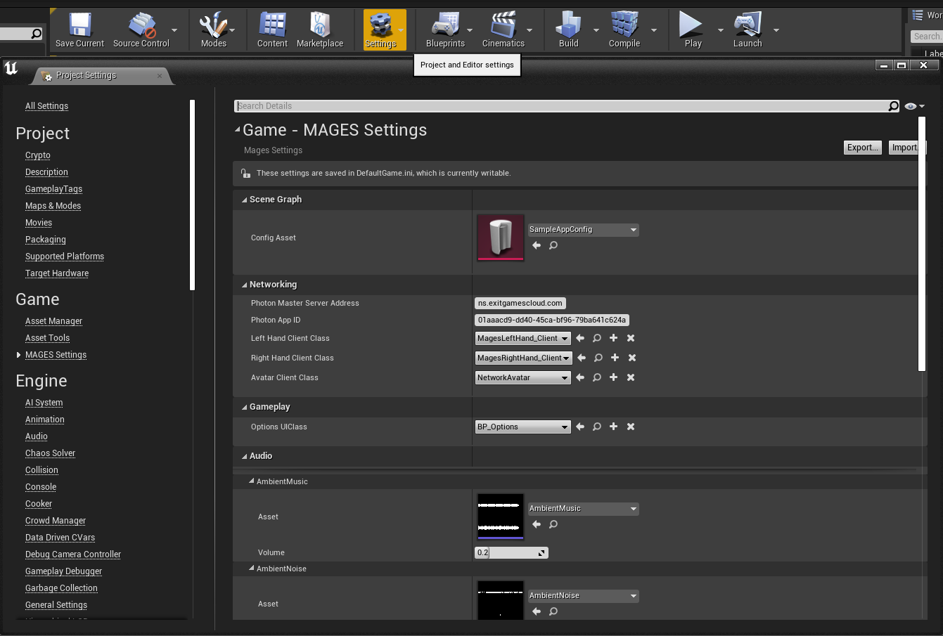
Ensure that the “Config Asset” property is set to “SampleAppConfig”, by clicking on the field, selecting “Clear”, and then resetting it to “SampleAppConfig” in the same manner
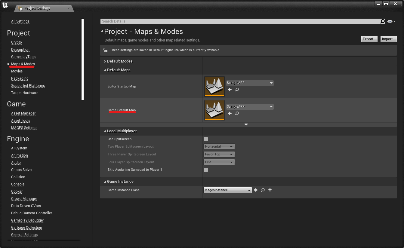
In the Maps & Modes section, ensure that the “Game Default Map” property is set to the “Sample App” map
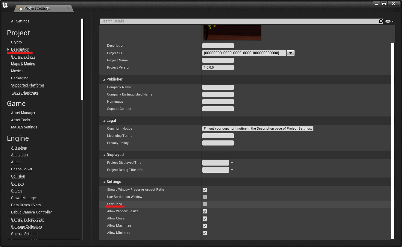
In the “Description” section, ensure that “Start in VR” is disabled:
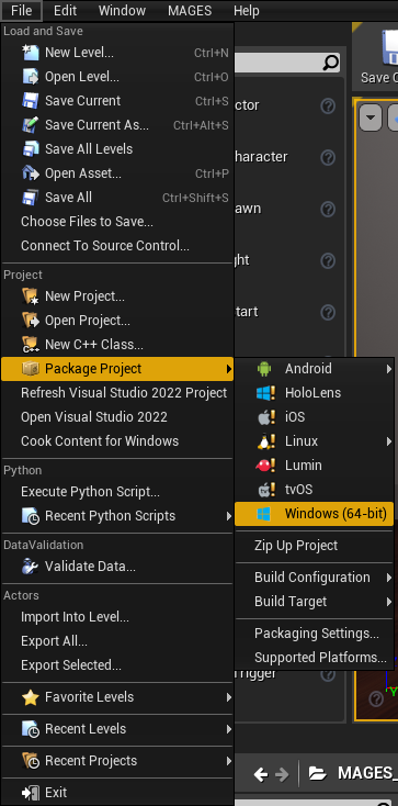
Close the Project Settings window, and in the level editor select “File > Package Project > Windows (64-bit)”
Note
For more information regarding packaging using the MAGES SDK and all of the supported platforms, please visit Build Instructions